Inspection (1000 hours)
When the wear pads are worn to 6 mm (0.23 in) or below
they should be replaced.
It is permissible to rotate the top wear pads 180° to prolong
service life, provided the contact surface is more than 6 mm
(0.23 in) thick.
Note: If rotating the wear pad the grease nipples will have to be swopped over.
Dismantling
1
Park the machine on firm level ground, engage the
parking brake and set the transmission to neutral.
Lower the loader arms to the ground.
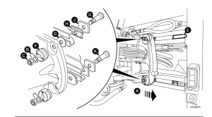
2
Set the carriage fully to end of travel A, shown in centre
position for clarity.
3
Lower the bucket to take the weight off the kingpost.
4
Switch OFF the engine and remove the starter key,
operate the control levers to vent residual hydraulic
pressure.
5
Unlock top lock tab B and unscrew nut C.
6
Remove bolt D through the slot in the rail E.
7
Hydraulic clamp F and washer G should remain in
position.
8
Remove plate J and wear pad H.
Assembly
9
Fit wear pad H, plate J and bolt D.
10
Fit new lock tab B and fit nut C.
11
Set the hydraclamp clearance as described in Sideshift
– Hydraclamp Clearance Setting.
12
Repeat procedure steps 5 to 11 for the bottom clamp.
The only difference on the bottom clamps is the wear
pad is on the opposite side of the rail from the top
clamp so bolt K need not be completely removed.
Note: If the wear pad is trapped between the rail and
carriage, lower the bucket to relieve the load on the wear
pad.
13
Lift the bucket and set the carriage to the opposite end
of the travel, repeat the procedure for opposite side.
14
When all clamps have been assembled recheck the
hydraclamp clearance of all clamps.