① Remove the crankshaft front oil seal, see Figure 2-111. (1) Disassembly of the crankshaft pulley and damper: When disassembling, first remove one mounting bolt, install one guide pin, and then remove the remaining bolts, pulley, and damper, see Figure 2-110. Do not use a hammer or screwdriver when disassembling the viscous damper to avoid damaging it.
(2) Disassembly of the idler assembly ① Remove the crankshaft front oil seal, see Figure 2-111.
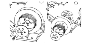
Figure 2-110 Disassembly of the crankshaft pulley and damper
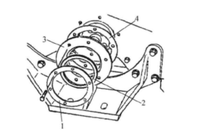
Figure 2-111 Disassembly of the crankshaft front oil seal 1—Pressure ring 2—Seal 3—Oil seal 4—Gasket
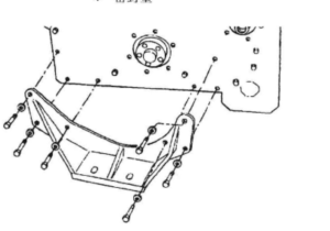
② Remove the engine front bracket, see Figure 2-112.
③ Remove the gear chamber cover and rectangular sealing ring, see Figure 2-113.
④ The engine is equipped with three idler wheel assemblies, see Figure 2-114. These three idler wheels are the water pump and oil pump idler wheels, the camshaft idler wheel, and the hydraulic pump idler wheel. Remove the camshaft idler wheel and water pump idler wheel in the order of the parts shown in Figure 2-11
5. If using an SAE “B” type hydraulic pump drive, mark the position of the idler wheel shaft when removing it. During reassembly, each shaft should be reinstalled in its original position.
6. Remove the hydraulic pump drive in the order of the parts shown in Figure 2-116.