(1) Overview of Static Injection Timing
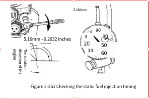
① Static injection timing must be set correctly to achieve optimal engine performance, fuel economy, and minimum emissions. Static injection timing must be checked after each engine overhaul and after each replacement, disassembly, or installation of gear train components, as shown in Figure 2-261.
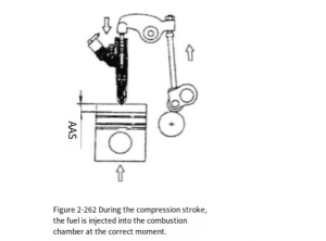
② Static injection timing refers to the timing at which fuel is injected into the combustion chamber during the compression stroke, as shown in Figure 2-262. Static injection timing must be checked when the piston is 5.16 mm before top dead center (BTDC) of the compression stroke. When the piston is in this position, the remaining stroke of the injector pushrod is measured using an injector timing tool with part number 3823451.
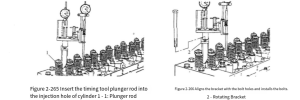
① Insert the plunger rod 1 of the fuel injection timing tool (part number 3823451) into the injector hole of cylinder 1, as shown in Figure 2-265.
② Align the rotating bracket 2 with the injector fixing bolt hole, see Figure 2-266, and pass the rotating bracket through the mounting bolt.
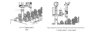
③ Tighten bolt 3, but do not overtighten (see Figure 2-267).
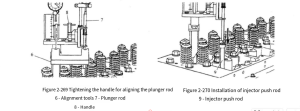
④ Position the pushrod plunger bracket on the timing tool behind the center bracket (see Figure 2-268). Use the alignment tool to center the pushrod plunger rod; after centering, tighten the handle (see Figure 2-269), and remove the alignment tool.
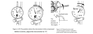
6. Install the injector pushrod between the injector cam follower and the plunger, as shown in Figure 2-270. Rotate the accessory drive shaft clockwise in the engine rotation direction to determine the piston position at top dead center of compression, as shown in Figure 2-271.
7. Check the static injection timing by rotating the crankshaft using only the accessory drive shaft to ensure accurate static timing.
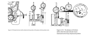
8. Place the dial indicator probe at the center of the plunger rod and move the dial indicator downwards to within 0.63 mm of the fully compressed position, as shown in Figure 2-272.
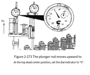
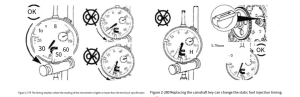
9. When the plunger rod moves upward to the top dead center (TDC) position, adjust the dial indicator to “0” (see Figure 2-273).
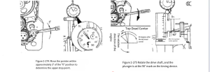
10. Rotate the drive shaft back and forth, moving the dial indicator pointer approximately 3° before and after the “0” position to confirm the piston is at the top dead center (TDC) position (see Figure 2-274).
11. Rotate the accessory drive shaft clockwise to a position 90° after TDC (ATDC) (see Figure 2-275). The plunger will then be at the 90° mark on the timing device.
12. Place the dial indicator probe at the center of the plunger rod, causing the dial indicator to move downward to within 0.63 mm of the fully compressed position. Adjust the dial indicator to “0” (see Figure 2-276), and then move it counterclockwise along the crankshaft.
13. Rotate the accessory drive shaft in the clockwise direction to top dead center (TDC). Rotate the accessory drive shaft counterclockwise until the crankshaft is 45° before top dead center (BTDC), as shown in Figure 2-277. The purpose of this step is to eliminate engine backlash.
14. If the crankshaft rotates more than 5.160 mm before top dead center (TDC), it must be rotated counterclockwise back to 45° before TDC. Then rotate the drive shaft clockwise until the dial indicator reading is 5.160 mm before TDC.
15. Read the dial indicator reading counterclockwise from “0”. This stroke is the static injection timing value, see Figure 2-278. The static injection timing value in the figure is 5.97 mm.
16. To verify the correctness of the engine’s static injection timing, check the CPL number on the engine nameplate and refer to the Control Parts Catalog (CPL) (part number 3379133) for verification. Figure 2-278 Reading
17. If the dial indicator reading is higher than the technical specification, it indicates timing retardation; if the dial indicator reading is lower than the technical specification, it indicates timing advance, see Figure 2-279.
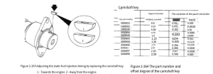
18. The static injection timing can be changed by removing the camshaft gear and installing a camshaft key, as shown in Figure 2-280.