Removal
1
Park the machine on firm level ground, apply the
parking brake. Lower the loader arms and excavator to
the ground, switch OFF the engine and remove the
starter key.
JCB Electronic Service Tool Diagnostic Kit High Quality
2
Disconnect the battery.
3
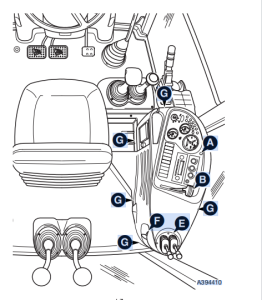
Working in the cab, remove the fixing A at the top of the
instrument panel and carefully lift the panel forward to
reveal the connections at the back as shown.
JCB ServiceMaster/WinEEM4 KG v2 Keygen
4
Disconnect the electrical connectors and heater
controls cables at the rear of the instrument panel, then
remove the instrument panel assembly clear of the side
console. Label the connectors and controls cables
before disconnecting to ensure correct replacement.
5
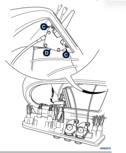
Remove the hand throttle lever knob B, remove the
screws C from the hand throttle lever and mounting
bracket assembly D inside the side console as shown.
Withdraw the handle through the slot in the panel.
6
Remove the screws from around the base of the
stabiliser control levers E, carefully withdraw the lever
assembly from the side console and disconnect the
control cables from the underside. Label each control
cable before disconnecting to ensure correct
replacement.
07.2026 JCB ServiceMaster 4 v26.7.1 Diagnostic Software with SW Files Download and installation
7
Unscrew the knob and lock nut from the boom lock
control F.
8
Remove the fixings G (5 off) securing the side console
panel at positions shown. Carefully lift up the rear
corner of the side panel over the boom lock control
outer sleeve, and then lift the side panel clear.
Replacement
Replacement is the reverse of the removal sequence.
Take care when removing/replacing the console panel to
ensure that harnesses do not become snagged and that no
other connections have been disturbed.
After re-fitting, operate the side console controls and check
they all function correctly.