
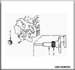
1.Install the crankshaft gear.
a.Install the crankshaft gear.
b.Use the crankshaft gear installer(1)to install the crankshaft gear(2).
The crankshaft gear timing mark(“.-·”)must be facing outward.
Special tool:
Crankshaft Gear Installer:9-8522-0020-0
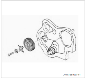
2.Install the camshaft timing gear.
a.Install the thrust plate to the cylinder body.
b.Tighten the thrust plate bolts to the specified torque.
Tightening torque: 19 N·m(1.9 kg·m/14 Ib·ft)
c.Install the camshaft timing gear to the camshaft.
The timing gear mark(“:-:”)must be facing outward.
d.Install the cam angle rotor to the camshaft timing gear.
The identification mark must be facing outward.
e.Tighten the timing gear to the specified torque.
Tightening torque: 110 Nm(11.2 kg·m/81 Ib·ft)
3.Install the fuel supply pump.
Refer to “Fuel Supply Pump”in Section 6C,Engine
Fuel.
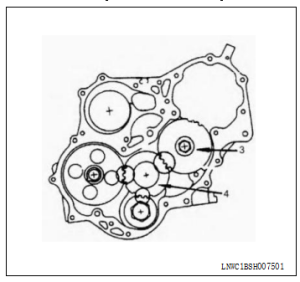
4.Install the idle gear.
a.Apply engine oil to the dler gear and the idler
gear shaft.
The idler gear shaft oil hole must be facing up.
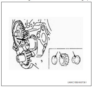
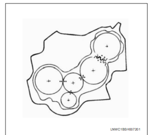
b.Position the idler gear setting marks”.”and”:”
so that they are facing the front of the engine.
c.Align the idler gear”.”setting mark with the
crankshaft timing gear(1)”-.”setting mark.
d.Align the idler gear”:”‘setting mark with the
camshaft timing gear(2)y”::”setting mark.
e.Install the thrust collar and bolts to the cylinder
body through the shaft.
The thrust collar oil hole must be facing up,and
the thrust collar chamferedmust be outward.
f.Tighten the idler gear bolt to the speafied
torque.
Tightening torque:
19 Nm(1.9 kg-m/14 Ib:t)
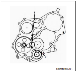
5.Install the idle gear.
a.Apply engine oil to the idler gear and the idler
gear shaft.
b.Align the idler gear B(3y”:”setting mark with
the idler gear A(4)“:-:“setting mark.
c.lighten the idler gear bolt to the specitied
torque.
Tightening torque:
76 Nm(7.7 kg:m/56 Ib-ft)
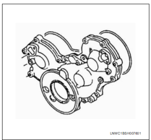
6.Install the timing gear case cover.
a.Alignthegearcasewiththetiminggear case
knock pin and then install the timing gear case
cover.
b.Tighten the gear case cover bolts to the
specified torque.
Tightening torque:
22 N·m (2.2 kg-m/16 Ib-ft)
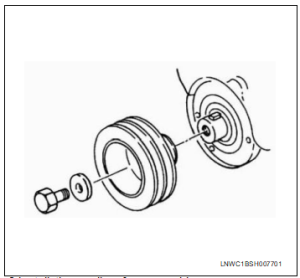
7.Installthe crankshaft damper pulley
·Tighten the crankshaft damper pulley bolt to the
specified torque.
NOTE:
Hold the flywheelringgear stationary toprevent the
crankshaft from turning when tightening the damper
pulley
Tightening torque: 294 N·m(30 kg:m/217 Ib:ft))
8.Install the cooling fan assembly.
·Mount fanpulley,distancepiece,andcooling
fan assembly (in this order)on the water pump,
and tighten to the specified torque
Tightening torque: 8Nm(0.8 kg:m/69 Ib-in)
9.Install the AC generator drive belt.
Refer to “Drive Belt”in Section 6B,Engine Cooling.
10.Install the power steering pump and bracket
assembly.
Refer to “Engine Assembly”in this Section.
11.Install the radiator.
Refer to “Radiator”in Section 6B Engine Cooling.
12.Refill the engine coolant.
13.Connect the battery cable negative terminal.